|
|
|
Overview:
|
|
Mailing list:
|
|
Design:
|
|
SourceForge:
|
Prototypes
The first prototype UAV is built on a Lite Machines 110 remote control helicopter. The choice of the LM-110 is an ideal platform for debugging both the autopilot and the command and control software. It has nearly indestructable, full flapping plastic rotor blades and can take nearly any abuse from "software bugs" or Pilot Error.
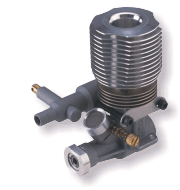
 Unfortunately, the 0.061 cubic inch (1cc) engine
(by Norvel, pictured on the left)
only produces about 0.1 horsepower. This is no where near enough
power to lift the airframe, engine, embedded computer, servo controller,
attitude gyros and camera. However, the larger aircrafts are very
expensive to crash, so they are cost prohibitive for testing.
The Enya-60 0.60 cubic inch (10cc) engine is on the right; it provides
enough power for a 5 kg payload, but consumes far more fuel.
Unfortunately, the 0.061 cubic inch (1cc) engine
(by Norvel, pictured on the left)
only produces about 0.1 horsepower. This is no where near enough
power to lift the airframe, engine, embedded computer, servo controller,
attitude gyros and camera. However, the larger aircrafts are very
expensive to crash, so they are cost prohibitive for testing.
The Enya-60 0.60 cubic inch (10cc) engine is on the right; it provides
enough power for a 5 kg payload, but consumes far more fuel.
![[ Testing the video feed ]](images/video-feed.jpg) Instead of having all of the hardware onboard, the prototype has
the servo controller connected to a laptop via a light serial
cable. This tether limits the functionality of the UAV, but
allows for easy debugging and off loads the underpowered LM-110.
It can barely carry the camera, full fuel, servo controller and
battery.
Instead of having all of the hardware onboard, the prototype has
the servo controller connected to a laptop via a light serial
cable. This tether limits the functionality of the UAV, but
allows for easy debugging and off loads the underpowered LM-110.
It can barely carry the camera, full fuel, servo controller and
battery.
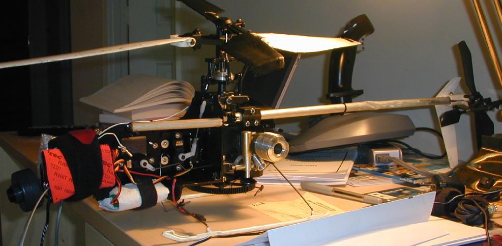
We now have new photographs of the first prototype with the camera head,
the ground station and the video feed. On the right is the video feed test
(click to zoom), showing the hotel room and television.
The boom is still dented and the gearbox split, which you can
see in the photograph at the top of the page
(click to zoom in)).
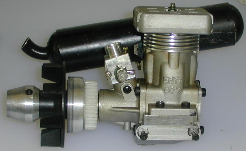
The new prototype is in the process of being built. Some parts are on order, others are currently being modified. They are:
 Kyosho Concept 60
The LiteMachines is a great beginning helicopter. But it lacked the
payload capacity for the full onboard system and autopilot, so a larger
model was required. The Concept 60 has a 10 cc engine and a payload
capacity of about 4 kg. The comparison between the first and second
geneneration prototypes is quite amazing, as seen in these images:
![[ Rotor diameter ]](images/comparison-blades.jpg) The rotor diameter of the Concept 60 is over twice that of the LMH.
This leads to over four times the blade area and lifting surface.
The rotor diameter of the Concept 60 is over twice that of the LMH.
This leads to over four times the blade area and lifting surface.
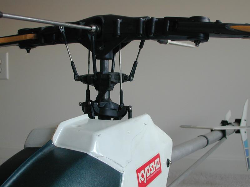
![[ Kyosho 60 head ]](images/comparison-head-60.02.jpg)
![[ LiteMachines 110 head ]](images/comparison-head-lmh.jpg) The Kyosho head is pictured on the right and the LiteMachines on the left.
The simpler head of the LMH is due to its lack of any collective controls,
while the more complex rotorcraft needs the ability to change the pitch
of all blades at the same time in order to maintain a constant RPM.
Here is an alternate image of the
Kyosho head.
The Kyosho head is pictured on the right and the LiteMachines on the left.
The simpler head of the LMH is due to its lack of any collective controls,
while the more complex rotorcraft needs the ability to change the pitch
of all blades at the same time in order to maintain a constant RPM.
Here is an alternate image of the
Kyosho head.
![[ Side views ]](images/comparison-side.jpg) The height is also quite a bit taller. You can see the engine heatsink
on the LMH quite clearly. The Kyosho has an active cooling system
that uses an engine driven fan to force air over the head, but it is
enclosed inside the mainframe.
The height is also quite a bit taller. You can see the engine heatsink
on the LMH quite clearly. The Kyosho has an active cooling system
that uses an engine driven fan to force air over the head, but it is
enclosed inside the mainframe.
![[ Top views ]](images/comparison-top.jpg) The Hiller paddle and fly bar on the Kyosho are almost as large
as the main rotor on the LMH. The Bell/Hiller subrotor on the LMH
is clearly visible.
The Hiller paddle and fly bar on the Kyosho are almost as large
as the main rotor on the LMH. The Bell/Hiller subrotor on the LMH
is clearly visible.
![[ View of the left side engine compartment ]](images/clearance-left.jpg)
![[ View of the right side engine compartment ]](images/clearance-right.jpg) The engine, clutch, transmission and gearbox are all enclosed in tightly
fitting plastic ducting. This means that it will be difficult to
add onboard electrical power generation (such as the
Genesys
from
Sullivan Products
). As you can see from the left and right side pictures (click to
zoom in), there is very little room for the alternator disk and
pickup. It's not even clear where to mount the HAL effect sensors
for the N1 and N2 tachs.
The engine, clutch, transmission and gearbox are all enclosed in tightly
fitting plastic ducting. This means that it will be difficult to
add onboard electrical power generation (such as the
Genesys
from
Sullivan Products
). As you can see from the left and right side pictures (click to
zoom in), there is very little room for the alternator disk and
pickup. It's not even clear where to mount the HAL effect sensors
for the N1 and N2 tachs.
Atmel AVR
![[ STK200 proto-board ]](images/stk200.jpg) The real-time tasks onboard are handled by the AVR Mega103 microcontroller.
It has 64 IO lines, PWM output, a UART and is supported by gcc.
Makes a great development environment. The image on the left is
of the prototyping board; the production system will have custom
PCB's rather than using the large proto-board. The actual controller
is the small raised portion in the upper left corner. The image on
the right is the custom wire harness to interface with a HiTec receiver,
some number of gyros and eight servos. (Click on either image to zoom)
The real-time tasks onboard are handled by the AVR Mega103 microcontroller.
It has 64 IO lines, PWM output, a UART and is supported by gcc.
Makes a great development environment. The image on the left is
of the prototyping board; the production system will have custom
PCB's rather than using the large proto-board. The actual controller
is the small raised portion in the upper left corner. The image on
the right is the custom wire harness to interface with a HiTec receiver,
some number of gyros and eight servos. (Click on either image to zoom)
![[ Servo interface ]](images/stk200-servos.jpg)
The realtime tasks that it will handle are:
- Servo sampling (for the safety pilot receiver) [Done]
- Gyro sampling (and rate integration for the AHRS) [Done]
- Read engine and control sensors (tach, etc)
- Read NMEA data from the GPS
- Output PWM signals for the control surface servos [Done]
- Output PWM signals for the payload controls [Done]
- TTL interface to the payload, if necessary
- Write summary data to the nav/autopilot system on the serial port. [Sort of done]
- Read commands from the nav/autopilot system from the serial port. [Sort of done]
Suspicious.org's embedded 486
![[ Embedded 486 ]](images/embedded.jpg) They build embedded BSD machines for firewalls. Power consumption
is a little high at 10 W, but it has GPIO lines, serial console
support, and a mini-PCI slot. The formfactor will require a fairly
large airframe. No board has yet been ordered; the prototype is
still tethered to the ground. We will most likely move to the
onboard system once the command and control software is more
mature. No sense in wrecking a large helicopter with the onboard
system before we're ready.
They build embedded BSD machines for firewalls. Power consumption
is a little high at 10 W, but it has GPIO lines, serial console
support, and a mini-PCI slot. The formfactor will require a fairly
large airframe. No board has yet been ordered; the prototype is
still tethered to the ground. We will most likely move to the
onboard system once the command and control software is more
mature. No sense in wrecking a large helicopter with the onboard
system before we're ready.
AHRS
![[ EFIS screenshot ]](images/curves-efis.gif) No low-cost "Attitude / Heading / Roll System" has been found, so we've
design our own IMU.
Of the commercially available choices, the one from
PC Flight Systems
might work. It uses MEMS gyros and
accelerometers to computer the attitude of the sensors. They have
an RS-232 port and software for WinCE. Rough cost is $1,400.
No low-cost "Attitude / Heading / Roll System" has been found, so we've
design our own IMU.
Of the commercially available choices, the one from
PC Flight Systems
might work. It uses MEMS gyros and
accelerometers to computer the attitude of the sensors. They have
an RS-232 port and software for WinCE. Rough cost is $1,400.
![[ Custom IMU, top view ]](images/pcb-top.03.jpg) Another option is to purchase three piezo gyros and use GPIO lines
to read the results. It would load the system a bit more to
poll the accelerometers, but the cost would be in the $300 range.
This option was tried and discarded in favor of building a home
brew IMU with gyros, accelerometers and a microcontroller to
perform the rate integration. It is visible on the left, partially
populated with one dual axis gyro and one dual axis accelerometer
(click to zoom in).
Another option is to purchase three piezo gyros and use GPIO lines
to read the results. It would load the system a bit more to
poll the accelerometers, but the cost would be in the $300 range.
This option was tried and discarded in favor of building a home
brew IMU with gyros, accelerometers and a microcontroller to
perform the rate integration. It is visible on the left, partially
populated with one dual axis gyro and one dual axis accelerometer
(click to zoom in).
You can see a screen shot from the curves program from the 1.5 release. It samples the gyros and performs rate integration on board. The results are then sent to the ground station for display with the EFIS::AI widget.
The
MIT project
used the
Crossbow IMU,
but the single unit prices are in the $4,000 to $6,000 range.
I've written
a survey of the available units.
The first prototype was built in September 2001 and flown under manual control via the computer in October. It consisted of:
Lite Machines 110
As described above...
Mini-Servo Controller
![[ Mini-SSC ]](images/ssc2.jpg) Rather than consuming all of the GPIO lines on the board, this device
can control eight servos. It has a very simple programming interface
and can be used with minimal software over a serial port. A major draw
back is that it requires an extra battery, something the LM-110 has
trouble carrying. Luckily the power draw is very low and it can share
the 7.2V cell with the xcam. 20 mA at 9V is not bad.
Rather than consuming all of the GPIO lines on the board, this device
can control eight servos. It has a very simple programming interface
and can be used with minimal software over a serial port. A major draw
back is that it requires an extra battery, something the LM-110 has
trouble carrying. Luckily the power draw is very low and it can share
the 7.2V cell with the xcam. 20 mA at 9V is not bad.
Logitech Wingman
![[ Wingman ]](images/wingman.gif)
![[ The ground station ]](images/gs-inside.jpg) It's cheap, USB and has four axes. The stick twists, which I have mapped
to the anti-torque pedals. More details are in the
README.
The buttons provide a force-release style trim (implemented by the
flyer
program).
You can see the ground station in the photograph on the right with the
Release 1.1
version running.
It's cheap, USB and has four axes. The stick twists, which I have mapped
to the anti-torque pedals. More details are in the
README.
The buttons provide a force-release style trim (implemented by the
flyer
program).
You can see the ground station in the photograph on the right with the
Release 1.1
version running.
X-10 wireless camera
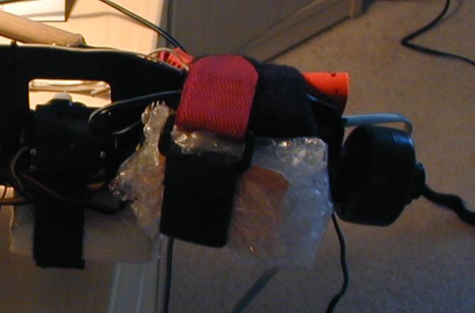
![[ xcam2 kit ]](images/xcam.gif)
![[ The Camera head ]](images/camera-head.jpg) Yes, I bought one. But not with that damn pop-under ad. Quality
is low, but the cost is too. Power consumption isn't too bad,
about 80 mA at 9V. You can see it mounted on the body to the
right (click to zoom in). Also visible in the photograph is the
relocated 4.8V battery (underneath the keel).
Most of the body and housing was removed to make it
easier to mount. You can see the camera itself bolted to the
keel. In
this picture
you can see the antenna wrapped in bubble wrap and secured to
the keel.
Yes, I bought one. But not with that damn pop-under ad. Quality
is low, but the cost is too. Power consumption isn't too bad,
about 80 mA at 9V. You can see it mounted on the body to the
right (click to zoom in). Also visible in the photograph is the
relocated 4.8V battery (underneath the keel).
Most of the body and housing was removed to make it
easier to mount. You can see the camera itself bolted to the
keel. In
this picture
you can see the antenna wrapped in bubble wrap and secured to
the keel.