|
|
|
Overview:
|
|
Mailing list:
|
|
Design:
|
|
SourceForge:
|

Strapdown IMU
For background on what IMU, INS and AHRS actually mean, here is a good overview.
Current version
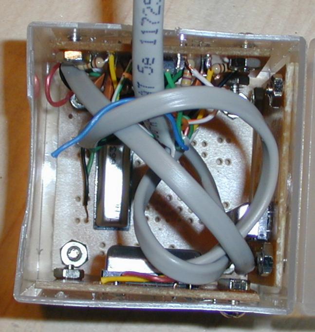 The current version of the IMU is built with three Murata ENC-05E
angular rate sensors scavenged from older versions of the
Gyration GyroPoint mice.
The analog signals are filtered and amplified by a quad opamp
in the sensor package, with a circuit
borrowed from the GyroPoint mice.
The current version of the IMU is built with three Murata ENC-05E
angular rate sensors scavenged from older versions of the
Gyration GyroPoint mice.
The analog signals are filtered and amplified by a quad opamp
in the sensor package, with a circuit
borrowed from the GyroPoint mice.
There is also room for two
ADXL202-EB accelerometers, although
only the pitch and roll unit is currently installed.
Also planned is a small one axis magnetometer and temperature
sensor to better calibrate the gyros.
 The schematic for the filter is:
                   ____
                  |    \
  Reference ------| +   \
                  |      >----+------  Output
  Gyro -/\/\/\-+--| -   /     |
         R1    |  |____/      |
               |              |
               |     R2       |
               +---/\/\/\/----+
               |              |
               +----||--------+
                    C1
R1 is 10k
R2 is 47k Ohm
C1 is 0.47 uF
The "real world" data from the
sensors is fed into a
Kalman filter.
This combines the various inputs and their estimates of the current attitude
to produce a better estimate with much of the noise filtered out.
Here is our
overview of Kalman filtering
and our
source code
to perform the math.
It currently takes place on the ground station, but once we have a faster
MCU or the embedded Linux system this will be moved to onboard the aircraft.

Onboard version
We had a three axis version built on the
custom PCB
using two MG100's and two ADXL202-EB's. This worked fairly well, although
some RFI and ADC sensitivity issues prevented it from detecting small
rotations. The IMU above amplifies the signal to help with that problem.
The other issue is that the circuit board needed to be properly aligned, which
caused some problems with the smaller of the two
prototypes.
The separate IMU can more easily be positioned and "strapped down"
to keep the reference frame fixed.
Two-axis version
 Our previous version was a two-axis strapdown unit that consisted of a
Gyration MG100
(pictured on the left)
combined with a
ADXL202-EB.
The MG100 is a small, 2cm x 2cm x 2cm and low power (20 mA @ 3.3V) two axis
rate gyroscope. It has low drift and temperature compensation,
but high precession errors under G loads.
Easy interfacing via analog voltage sampling.
$58 in single unit quantities (including a full PS/2 mouse and parts!).
It is the silver components pictured to the left on the factory board and
below on the right mounted in the custom two-axis IMU.
Source code
for
sampling the MG100
is available.
Our previous version was a two-axis strapdown unit that consisted of a
Gyration MG100
(pictured on the left)
combined with a
ADXL202-EB.
The MG100 is a small, 2cm x 2cm x 2cm and low power (20 mA @ 3.3V) two axis
rate gyroscope. It has low drift and temperature compensation,
but high precession errors under G loads.
Easy interfacing via analog voltage sampling.
$58 in single unit quantities (including a full PS/2 mouse and parts!).
It is the silver components pictured to the left on the factory board and
below on the right mounted in the custom two-axis IMU.
Source code
for
sampling the MG100
is available.
 The rate integration isn't very accurate, so we augment it with
a dual axis accelerometer. The
ADXL202
(+/-2) is an inexpensive MEMS device ($30 in single unit quantities).
It is the small board on the left of the IMU pictured to the right.
Source code
for
sampling the ADXL
is available, too.
The rate integration isn't very accurate, so we augment it with
a dual axis accelerometer. The
ADXL202
(+/-2) is an inexpensive MEMS device ($30 in single unit quantities).
It is the small board on the left of the IMU pictured to the right.
Source code
for
sampling the ADXL
is available, too.
Just a reminder -- all our source is available.
If you're interested in other AHRS / INS options, here is a
short overview
of different possibilities.