|
|
|
Overview:
|
|
Mailing list:
|
|
Design:
|
|
SourceForge:
|
Custom PCB
![[ Bottom view of the unpopulated custom PCB ]](images/pcb-bottom.01.jpg) The real-time system was mounted on an
STK300 development board
from Atmel, but we want to have a custom board
for cleanliness and smaller size reasons. Several
members of the project
have experience with PCB layout and design.
The bottom of the Rev 1.0 board is pictured, unpopulated,
on the left. There were a few
big mistakes
made in the Rev 1.0 board, so please do not fabricate them without
checking the notes. If you want to fix any of the problems, that would
be good, too.
The real-time system was mounted on an
STK300 development board
from Atmel, but we want to have a custom board
for cleanliness and smaller size reasons. Several
members of the project
have experience with PCB layout and design.
The bottom of the Rev 1.0 board is pictured, unpopulated,
on the left. There were a few
big mistakes
made in the Rev 1.0 board, so please do not fabricate them without
checking the notes. If you want to fix any of the problems, that would
be good, too.
The next rev of the boards is being design right now. It has an AT91, an FPGA, wireless serial and lots of other nice features. We're hoping to have them laid out and built by summer of 2002.
We've selected
ExpressPCB
for the fabrication. They have a three-day turnaround from the time that
they receive an order to having the finished product delivered, for $20
a board. We can fit everything on to the small board for that special
price. In addition to the PCB and
![[ PCB layout ]](images/pcb.png) AVR Mega16,
you will require an IMU or AHRS. We have
designed an IMU
that consists of a
two-axis rate gyroscopes
from
Gyration,
and
ADXL202-EB
from
Analog.
The new design of the board fits the entire IMU, servo controller
and safety pilot switch onto a single board.
Of course, a
remote control helicopter
is also necessary.
AVR Mega16,
you will require an IMU or AHRS. We have
designed an IMU
that consists of a
two-axis rate gyroscopes
from
Gyration,
and
ADXL202-EB
from
Analog.
The new design of the board fits the entire IMU, servo controller
and safety pilot switch onto a single board.
Of course, a
remote control helicopter
is also necessary.
The PCB layout program from ExpressPCB is "free-as-beer" and can be downloaded from their site. Unfortunately it only supports legacy operating systems. It can be run under Wine, so not all is lost. There are bugs in displaying thick traces, so be sure to check your layout against the Windows version.
Download our current layout, or look at the version history on the file.
![[ Servo interface ]](images/stk200-servos.jpg) Before the board was produced, we used a custom wiring harness that
breaks out the ports on the STK300 to connect the servos, the receiver
and the
IMU.
The wiring map for this is very simple -- A0 .. A7
connect to servo/gyro inputs and C0 .. C7 connect to the eight outgoing
servos.
Before the board was produced, we used a custom wiring harness that
breaks out the ports on the STK300 to connect the servos, the receiver
and the
IMU.
The wiring map for this is very simple -- A0 .. A7
connect to servo/gyro inputs and C0 .. C7 connect to the eight outgoing
servos.
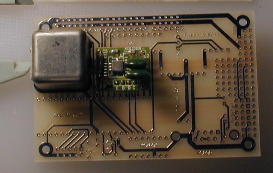
![[ Top view of the slightly populated custom PCB ]](images/pcb-top.03.jpg) The custom board has the servo connectors mounted directly on the board,
visible on the upper left of the partially populated board image. Eight are
for output, five are for input. There are also four analog inputs, two
pulse counting inputs
(for the
engine and rotor tachometer)
and five general digital IO inputs.
The IMU is entirely on the board, with two gyros and two
accelerometers.
One MG100 and one ADXL202-EB are installed in the image on the left.
Here is another image of the board with
calipers set to 25mm for scale.
The custom board has the servo connectors mounted directly on the board,
visible on the upper left of the partially populated board image. Eight are
for output, five are for input. There are also four analog inputs, two
pulse counting inputs
(for the
engine and rotor tachometer)
and five general digital IO inputs.
The IMU is entirely on the board, with two gyros and two
accelerometers.
One MG100 and one ADXL202-EB are installed in the image on the left.
Here is another image of the board with
calipers set to 25mm for scale.
There is one PAL on the board that performs the Safety-Pilot switching. Should the autopilot become confused or otherwise unable to maintain control, it can give control to a ground based pilot with a standard RC transmitter. Download the source for the PAL.

![[ IMU PCB ]](images/imu.pcb.png) The old IMU was mounted in RadioShack boxes on RadioShack protoboards and
connected via Cat5 to the IMU port on the STK200 board. Visible on the left
is the ADXL202-EB accelerometer and on the right is the MG100 rate gyro.
More details on the IMU
are available.
The PCB layout for the originally planned three-axis strapdown IMU is
on the left. The new design has the IMU built onto the same board as
the servo controller and safety pilot switch, removing over $20 per
unit cost.
The old IMU was mounted in RadioShack boxes on RadioShack protoboards and
connected via Cat5 to the IMU port on the STK200 board. Visible on the left
is the ADXL202-EB accelerometer and on the right is the MG100 rate gyro.
More details on the IMU
are available.
The PCB layout for the originally planned three-axis strapdown IMU is
on the left. The new design has the IMU built onto the same board as
the servo controller and safety pilot switch, removing over $20 per
unit cost.